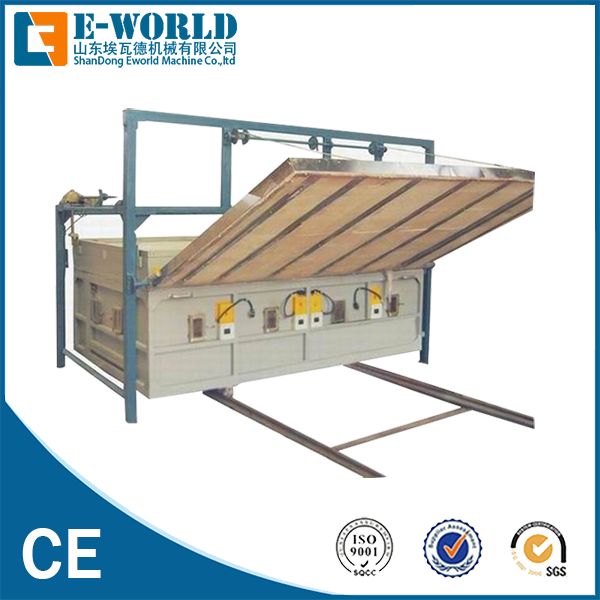
A Glass Melting Furnace stands as the most capital-intensive asset in a manufacturing plant. Its baseline performance heavily dictates your daily production capacity, energy overhead, and final product quality. Plant operators constantly face a difficult balancing act. You must maximize pull rates while proactively managing escalating energy costs. Stringent emission regulations and inevitable refractory wear add severe layers of complexity to this daily challenge. Running inefficient systems quickly erodes profit margins.
This guide provides plant managers, industrial engineers, and procurement teams with a definitive evaluation framework. We will explore various furnace architectures and unpack their specific operational tradeoffs. By the end, you will understand how to select the optimal system. This knowledge ensures long-term profitability and sustainable daily operations.
Key Takeaways
Design dictates economics: The choice between regenerative, oxy-fuel, and electric furnaces fundamentally alters the CapEx/OpEx ratio and environmental compliance strategy.
Thermal efficiency is not static: Working principles rely heavily on heat recovery systems and batch conditioning, where minor optimizations yield major fuel savings.
Refractories determine campaign life: Pairing the right refractory materials (e.g., fused cast AZS, silica) with the specific glass melt chemistry is critical to preventing premature furnace failure.
Selection requires holistic modeling: A successful procurement decision must balance target pull rates, local energy costs, space constraints, and lifecycle maintenance requirements.
Table of Contents
Toggle
How Glass Melting Furnaces Drive Production: Core Working Principles
Understanding the thermal science behind melting is essential. The core working principles define how raw materials transform into molten Glass. We must examine the specific conversion phases and thermal behaviors.
The Melting Cycle (Phases of Conversion)
We can break down the melting cycle into three distinct phases. Each phase requires precise control to guarantee product quality.
Batch Melting: This endothermic reaction converts raw silica and fluxes into a viscous liquid. The burner flames apply intense heat. The solid materials slowly dissolve and merge.
Fining: This critical phase removes gas bubbles, also known as seeds. Operators use chemical fining agents and precise temperature control here. The gases rise to the surface and escape. This ensures absolute clarity.
Homogenization & Conditioning: This phase applies thermal and mechanical balancing. It ensures uniform viscosity before the melt enters the forming process. Uneven temperatures cause severe forming defects.
Heat Transfer Dynamics
Thermal energy moves through the system in specific patterns. Radiant heat from burner flames transfers downward to the batch blanket. Crown reflections heavily assist this downward thermal transfer. You must evaluate these dynamics carefully.
Convection currents within the bath drive homogeneity. The hot liquid rises while cooler liquid sinks. Strong convection prevents stagnant dead zones from forming. These currents mix the chemical components thoroughly.
Energy Recovery Mechanisms
Modern furnaces recapture exhaust gas heat. They use this captured thermal energy to pre-heat incoming combustion air. This mechanism is an absolute requirement. It guarantees operational viability and lowers fuel consumption significantly. Without it, energy overhead becomes completely unsustainable.
Categorizing Glass Melting Furnaces: Evaluating the Options
Plants utilize several distinct architectures. Each design offers specific advantages for different production scales. Procurement teams must understand these structural differences.
Regenerative Furnaces (End-Fired & Cross-Fired)
This design uses alternating refractory checkerwork chambers to recover heat. Exhaust gases heat one chamber while incoming air cools the other. It remains the industry standard for high-capacity container and flat Glass. The thermal efficiency is excellent.
However, these units require a massive physical footprint. Initial refractory costs run very high. Checkers remain susceptible to plugging over time. Alkali vapors condense and block the narrow passages. High-volume, continuous production thrives here. Physical space must permit the large layout.
Oxy-Fuel Furnaces
The system replaces ambient combustion air with purified oxygen. This completely eliminates nitrogen from the burn process. By removing nitrogen, you achieve a drastic reduction in NOx emissions. Operators often see up to a 30% reduction in fuel consumption.
The physical footprint shrinks considerably because you eliminate the regenerator chambers. However, you need a continuous, cost-effective supply of oxygen. Liquid oxygen deliveries or on-site generation add logistical complexity. Localized refractory wear often accelerates due to higher water vapor concentrations. Plants facing strict environmental regulations benefit most.
Electric Melting Furnaces (Cold Top)
Submerged molybdenum or tin oxide electrodes apply Joule heating directly within the bath. Electrical currents pass through the resistive liquid to generate intense heat. These systems achieve near-zero emissions. Thermal efficiency frequently reaches up to 85%. You gain superior volatilization control.
The cold batch blanket on top traps volatile components effectively. However, electricity costs often exceed fossil fuel costs regionally. Electrode campaign life tends to be shorter than traditional refractories. You must replace them periodically. Specialty Glass and fiberglass perform well here. Regions possessing abundant, cheap electrical grids also benefit greatly.
Recuperative Furnaces (Unit Melters)
These units utilize continuous metallic heat exchangers. They abandon alternating refractory chambers entirely. Hot exhaust continuously heats incoming combustion air through metal walls. You face lower initial capital investments. Operation is much simpler because airflow remains constant.
Build times decrease significantly. However, heat recovery efficiency falls below regenerative models. The metal exchangers cannot withstand the extreme temperatures seen in ceramic checkers. Mid-scale production lines under 100 tons per day fit perfectly.
Operational Comparison Metrics
Architecture Type
Thermal Efficiency
Physical Footprint
Primary Limitation
Regenerative
High
Very Large
Checker plugging over time
Oxy-Fuel
Very High
Moderate
Continuous oxygen costs
Electric (Cold Top)
Exceptional
Small
High grid electricity rates
Recuperative
Moderate
Small
Lower heat recovery capability
The Role of Refractories: Securing Furnace Longevity
A heavy-duty thermal vessel requires resilient structural materials. The refractory lining protects the outer steel shell. It also maintains internal temperature profiles.
Material Compatibility
Matching refractory chemistry to your specific Glass type prevents accelerated corrosion. For example, soda-lime reacts differently than borosilicate. Ignoring this chemistry leads to catastrophic premature failures. Chemical attacks erode blocks rapidly.
Key Zones and Material Selection
Engineers specify different ceramics for different structural zones. Each zone faces unique thermal and chemical stressors.
Melter Sidewalls & Bottom: These areas rely heavily on Fused Cast AZS (Alumina-Zirconia-Silica). This material offers maximum corrosion resistance against molten liquids.
Crown (Roof): Silica brick provides high-temperature structural integrity. Crucially, it avoids dripping harmful contaminants into the melt.
Regenerator Checkers: Operators use magnesia or high-alumina bricks here. They withstand severe thermal cycling and brutal alkali vapor attacks.
Risk Mitigation
Premium insulation layers drastically reduce heat loss. Better insulation directly extends your overall campaign life. Continuous melters often run for 10 to 15 years. Careful thermal management guarantees you reach this milestone. Operators must monitor exterior shell temperatures daily.
Key Evaluation Dimensions for Furnace Selection
Picking a new unit requires strict multidimensional analysis. A wrong choice burdens the facility for over a decade. We recommend analyzing four distinct operational pillars.
CapEx vs. OpEx Modeling
You must weigh the high upfront cost of regenerative refractories against alternatives. Oxy-fuel systems require ongoing oxygen generation expenses. You must balance these financial realities carefully. Regenerative models demand massive initial capital. Oxy-fuel models shift the burden to daily operating expenses. Electric systems depend entirely on local grid pricing. Smart procurement teams project these costs over a fifteen-year horizon.
Production Capacity (Pull Rate)
Engineers must size the melting area accurately. We measure this in square meters per ton. Over-forcing the system degrades product quality rapidly. It pushes un-fined material into the forming machines. It also accelerates refractory wear significantly. High pull rates increase convection speeds and sidewall erosion. You must match the physical footprint to your maximum daily target.
Environmental & Compliance Realities
Local emission caps dictate technological choices heavily. Strict limits on NOx, SOx, and Particulate Matter often force a transition. You may need to adopt oxy-fuel technology or implement electric boosting. Governments worldwide continue tightening industrial emission standards. Legacy systems often struggle to meet these new legal requirements. A proactive compliance strategy prevents future shutdown orders.
Fuel Flexibility and Security
Assess the availability of natural gas, electricity, and alternative fuels. Forecasted costs in your specific geographic location matter greatly. Supply chain disruptions can halt operations entirely. Relying on a single energy source carries immense risk. Many modern plants incorporate hybrid designs. They blend gas burners and electrical boosting. This flexibility allows operators to switch based on real-time market prices.
Implementation Realities: Mitigating Risk During Rollout
Building and launching a new system involves extreme risk. Minor engineering errors compound into massive operational failures. You must control the installation process rigidly.
Pre-Installation Engineering
Computational Fluid Dynamics (CFD) modeling is an absolute necessity. It validates thermal flow and exact burner placement. You must finalize these models before any physical construction begins. CFD reveals potential cold spots or excessive wear zones. Correcting these issues digitally costs nothing. Fixing them after construction costs millions.
The Heat-Up Schedule
Strict adherence to standard thermal expansion curves is mandatory. You must manage the initial heat-up with extreme caution. Rushing this phase causes catastrophic refractory cracking. Silica bricks expand dramatically at specific temperature thresholds. Operators use temporary burners to raise the heat incrementally. A proper heat-up sequence often takes up to two weeks. Patience here ensures structural integrity.
Commissioning Timelines
You must account for realistic downtime. A cold repair or new build typically requires 30 to 60 days. Operators need solid strategies to bridge these massive production gaps. You might stockpile inventory beforehand. Alternatively, you could shift production to sister facilities. Project managers must coordinate contractors perfectly. Any delay in refractory delivery extends the costly outage.
Conclusion
Selecting the ideal Glass Melting Furnace remains a delicate balancing act. You must satisfy capacity requirements, energy realities, and environmental compliance simultaneously. Ignore any single factor, and profitability drops.
Start by mapping your capacity and emissions constraints. This approach quickly filters out unviable types. Follow this mapping with a strict lifecycle cost analysis. Weigh capital expenses against daily operational demands.
Behind every high-efficiency, zero-defect production floor stands the precise machinery required to execute flawless fabrication and testing. As a premier manufacturer of high-reliability automated glass processing systems, E-world delivers the code-compliant, ruggedly engineered machinery and cutting-edge automation solutions needed to support heavy manufacturing pipelines globally. By pairing state-of-the-art technological design with extensive technical support, they help operators maintain absolute joint, surface, and structural integrity across demanding industrial setups.
We strongly encourage readers to commission a detailed thermal audit of their current operations. You should also consult a specialized engineering firm to initiate preliminary design modeling. Action taken today secures tomorrow's manufacturing profitability.
FAQ
Q: What is the typical campaign life of a continuous glass melting furnace?
A: A continuous glass melting furnace typically operates for 10 to 15 years before requiring a cold repair. Actual longevity depends on several dynamic variables. The daily pull rate, specific chemistry, and overall refractory quality heavily influence this lifespan. Consistently aggressive pull rates will significantly shorten the campaign life.
Q: Can an existing regenerative furnace be converted to oxy-fuel?
A: Yes, conversion is highly viable and increasingly common. This process requires significant structural modifications. You must remove the regenerator chambers entirely and thoroughly seal the superstructure. This conversion drastically reduces NOx emissions and shrinks the overall physical footprint of the unit.
Q: What is "electric boosting" and when is it used?
A: Electric boosting is an auxiliary heating method. It submerges electrodes directly into the bath of fossil-fuel furnaces. Operators use this technique to increase production capacity or improve thermal convection. It achieves these goals without expanding the physical footprint of the melter.
Q: How does glass cullet percentage affect furnace efficiency?
A: Higher ratios of recycled material, known as cullet, lower the required melting energy. Cullet melts at a significantly lower temperature than raw batch materials. This directly reduces fuel consumption, lowers stack emissions, and significantly extends the campaign life.